Giant rings are IN, right?
December 3, 2014I finished up the working modes of my ring, so rev1 of the software is done. Here’s what it does:
On TAP: shows a vocabulary word. On tap or double tap, shows definition.
On DOUBLE TAP: starts Pong game, paddle position set by tilt of accelerometer.
On UPSIDE DOWN SHAKE: says to consider a question, waits for upside down shake (or punch) to give a response.
On PUNCH: puts up a punch word and a couple rectangles for emphasis.
As long as the wires are secure, this all works pretty well. I still need to format some of the Magic 8 ball style responses. And I could go through the vocabulary words to make shorter (better) definitions. I can probably pick up about 50 words too (yay!). I may continue to get rid of nonsensical floating point stuff so I can put more definitions in. Oh, and I should check the power usage, I didn’t minimize the accelerometer’s draw.
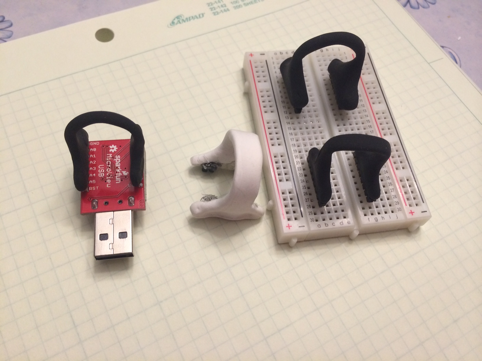
However, those tweaks can all wait as I need to make it wearable again. The button version was wearable but the ring blanks from that are a little too small for the accelerometer+battery stack up.
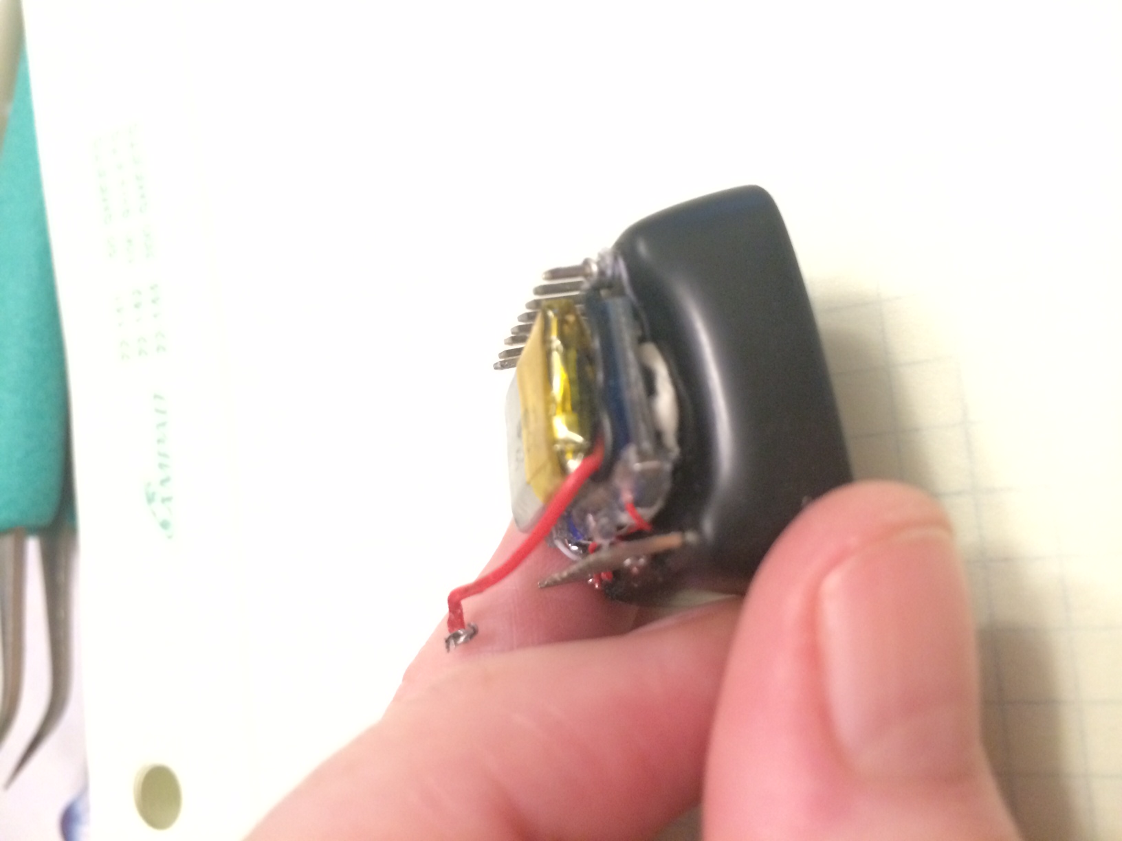
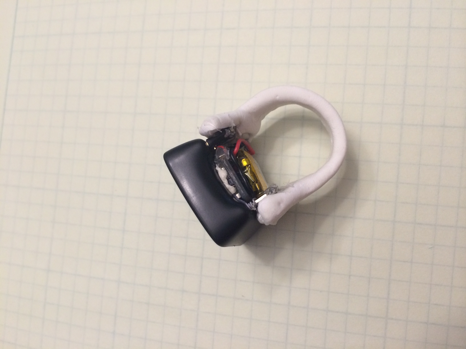
From another angle
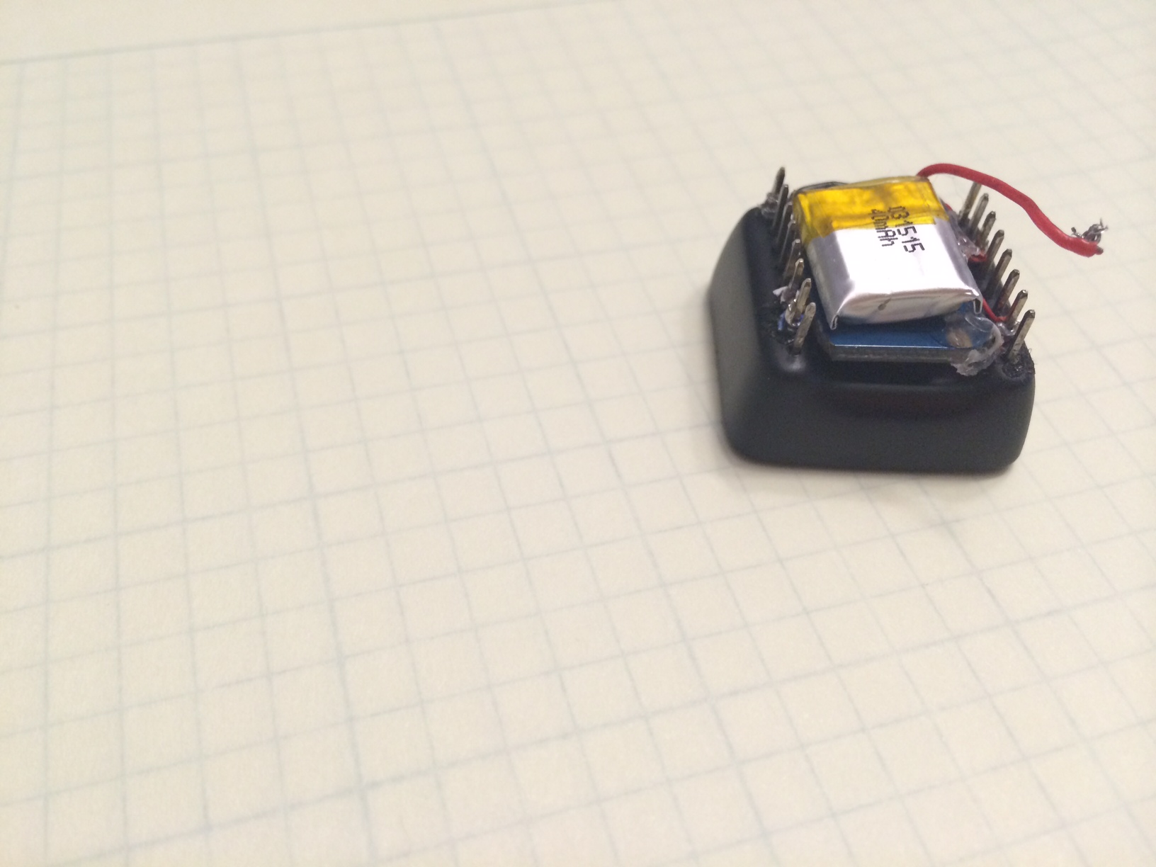
On the back of the MicroView is a dab of funtac (that stretchy sticky stuff you might have used to hang posters in your dorm room), a modified Adafruit 5V tolerant MMA8451 board (ahem, they didn’t need all that space for logos and mounting holes). Tiny wires are soldered to the board, then hot glued. On the other side, they are soldered to the MicroView.
On top of the accelerometer is a SparkFun 40mAh LiPo battery with its connector snipped. It is held on to the accelerometer with funtac (sometimes I build things entirely from funtac). I needed the battery on the outside so I can remove it for charging. The
This all stacks up higher than I wanted and doesn’t leave much space for attaching the ring to the device. With the button+battery version of the ring, I pressed the MicroView pins into the ring blank and press fit it all together. That doesn’t work so well now, especially as the poorly pressed fit doesn’t hold the power on.
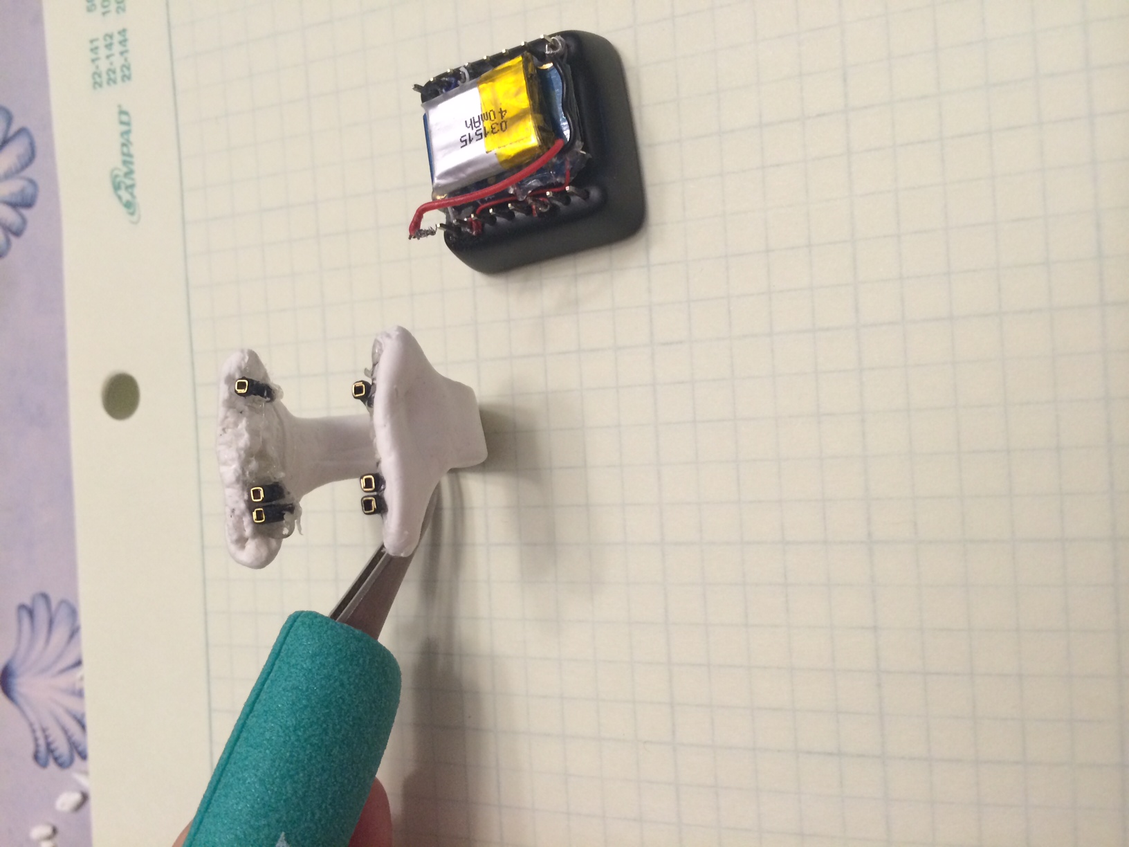
I snipped some jumper wire so I could build a connector on the inside of the ring blank. This was just a trial run. It worked out ok but I think I want to do something a little different for the real ones, maybe destroy 8 wires to get 16 connectors. Having attachments only on the pins of interest has some downsides (especially if I don’t line them up properly). More connector ends also lets me add some needed rigidity. Even these few fix the press fit problem. The female connectors are all too bulky though I may look around some more.
It doesn’t look too bad. Though I think the new black version are going to be better (still waiting for those to dry).
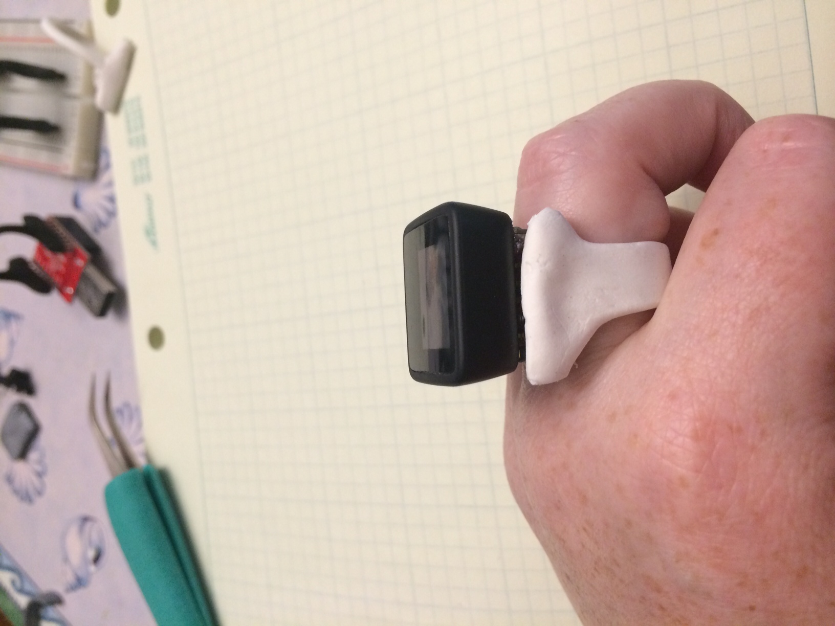
Well, let’s see it on!
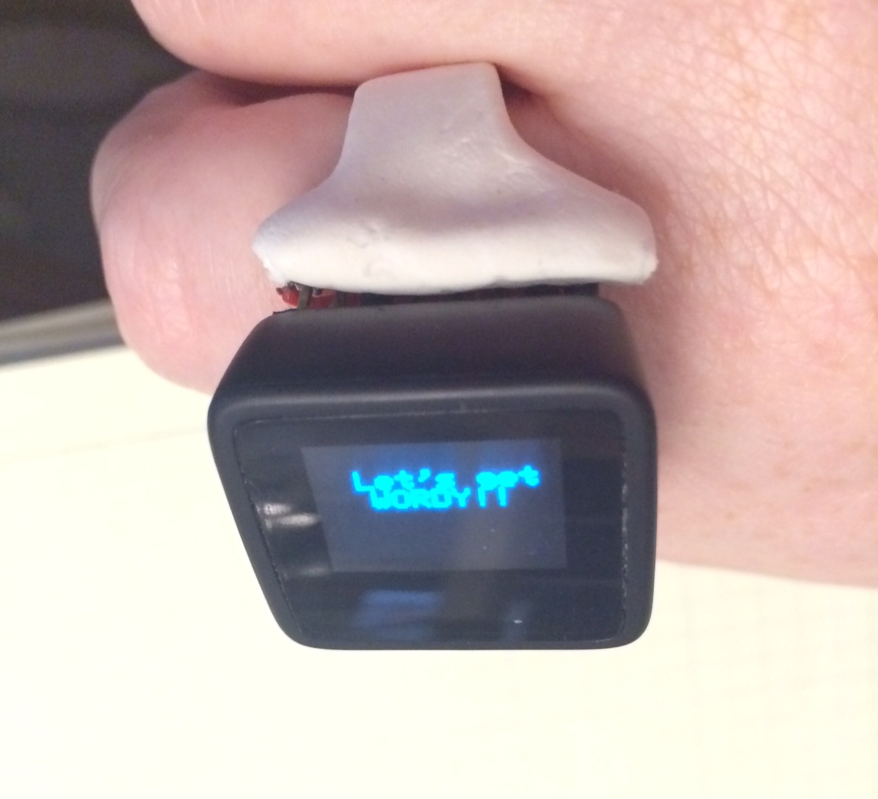 The 5s timeout on the screen makes it impossible to get an in-focus shot by myself. Ahh well, you get the idea. This angle is probably the nicest. From the side where you can see the stackup, not so nice. (Realistically, it wouldn’t be hard to cover this.)
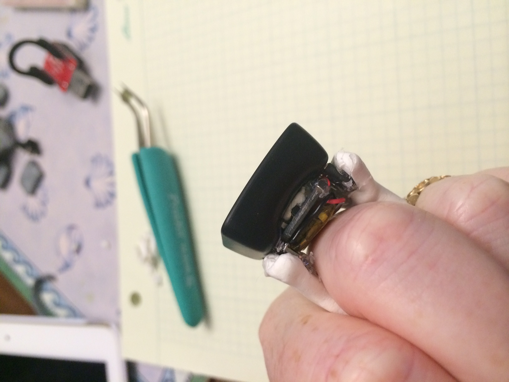
But I can’t leave it on that shot, one more, a little prettier.